Sheet Metal Fabrication Process Guide: The Complete Five-Stage Walkthrough
 Whether you are sourcing parts for the first time or reviewing an existing supply chain, a clear sheet metal fabrication process guide is the fastest way to understand what a supplier actually does with your drawing.
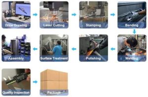
Every sheet metal part — from a simple bracket to a complex enclosure — moves through the same five stages: cutting, forming, joining, finishing, and inspection.
This sheet metal fabrication process guide walks through each stage, the tolerances you can reasonably expect, and what can go wrong.
What Are the Five Stages of Sheet Metal Fabrication?
Most custom sheet metal parts fit into these five main stages, but the actual process route adjusts with material, structure, quantity, and final application. Cutting produces the blank, forming creates the final geometry, joining completes assembly, finishing protects and improves appearance, and inspection confirms dimensions and quality. Each stage below covers the process, its typical tolerances, and the defects to watch for.
Stage 1 — Cutting: From Sheet to Blank
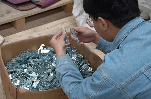
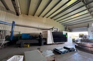 Cutting separates the required blank from the raw sheet. Three methods dominate: laser cutting for complex 2D profiles at low to medium volumes, stamping/blanking for high volumes with dedicated dies. Actual laser-cutting accuracy depends on material thickness, machine condition, geometry, and heat effects— confirm critical features against the specific drawing.
For specific thin sheets and critical features, we can evaluate manufacturability to ±0.05 mm against your drawing. Watch for burrs on laser-cut edges, heat-affected zones, and die roll-over on stamped blanks.
Stage 2 — Forming: From Blank to Shape
Forming gives the blank its 3D shape. Conventional CNC press-brake angle and dimensional tolerances depend on material, thickness, bend length, tooling, and geometry. Common engineering ranges are about ±0.5–1° for angles and ±0.2–0.5 mm for dimensions. Confirm critical dimensions in the specific drawing and process review.
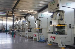
Stamping and deep drawing (up to 400 tons) form complex shapes at high volume with tighter positional tolerances. The main physics problem is springback — the material’s tendency to relax after bending — which is compensated by over-bending against accumulated material data. Watch for springback, thinning in deep drawing, and cracking along the bend line.
Stage 3 — Should a Part Be Welded or Mechanically Fastened?
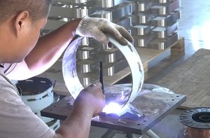 Joining assembles blanks into a final structure. MIG, TIG, spot, and laser welding are common options; mechanical methods—rivets, PEM fasteners, threaded inserts—avoid heat distortion entirely. When should you weld, and when should you use mechanical joining? For components requiring high structural strength, MIG/TIG welding creates a reliable connection; for thin-wall parts or distortion-sensitive structures, spot welding, clinching, or mechanical fasteners are sometimes the better choice. The decision cannot rest on equipment capability alone — deformation, appearance, strength, and downstream finishing all matter. Welded assemblies realistically hold ±0.5 mm or wider because heat causes distortion; the fix is sequencing, fixtures, and sometimes redesign. Watch for distortion, porosity, and burn-through.
Stage 4 — Finishing: Protecting the Surface
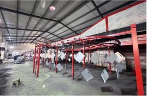
Finishing protects the part and sets its appearance. Powder coating provides durability and color. Plating, such as zinc or nickel, improves corrosion resistance. Anodizing is commonly used for aluminum. Other options include passivation and silkscreening. Pretreatment, including degreasing and phosphating, determines coating adhesion. The finishing line therefore matters as much as the coating itself.
Finishing is not a last-minute step. Consider it during material and structure design. Will liquid pool inside bends? Do welds need grinding? Do holes need masking? Does plating change dimensions? Do mating surfaces need protection after coating?
Watch for color mismatch and adhesion failure. Both can be traced to pretreatment.
Stage 5 — What Does Good Inspection Look Like Across the Process?
 Inspection closes the loop — but a mature fabrication process does not “check at the end”; it builds quality evidence at multiple points: incoming material, first article, in-process checks, final inspection, and batch traceability.
A first-article inspection (FAI) measures every critical dimension on the prototype; CMM machines verify production batches at the micron level; batch reports and material certificates travel with each shipment. Quality is only as good as the evidence — a process that produces parts but no documents is a process you cannot trust.
Putting the Sheet Metal Fabrication Process Guide to Work
Understanding the five stages turns a vague RFQ into a precise one. Inspection is where this sheet metal fabrication process guide proves its value — the process is only as good as the evidence it leaves behind. At each stage, ask the supplier:
- Cutting — Is the equipment owned, and is laser or stamping right for my volume? For tolerance details, see our precision sheet metal fabrication guide.
- Forming — How do you compensate for springback?
- Joining — How do you control weld distortion?
- Finishing — What pretreatment is included?
- Inspection — Are FAI and batch reports standard?
The answers separate a fabricator who runs the process from one who merely quotes it. For the services behind these stages, see our custom sheet metal fabrication services guide; for comparing suppliers end to end, our guide on choosing a China sheet metal fabrication manufacturer; and for why running every stage under one roof matters, the one-stop sheet metal fabrication model.
How We Run These Stages
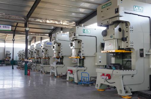
The five stages above are our daily production flow — and the equipment exists to serve the process route, not the other way around. At the cutting stage, two 6 kW laser cutters handle complex profiles and low-to-medium volumes, while 40+ stamping presses (up to 400 tons, including deep drawing) cover high-volume blanking — so different batch sizes and structures can each take the right route. At forming, a CNC press brake line executes every bend, with springback compensation data built from 70,000+ part numbers. At joining, in-house welding lines cover MIG, TIG, and spot welding.
At finishing, coating and pretreatment run on our own line. At inspection, CMM machines measure at the micron level; every prototype ships with FAI, and every batch ships with inspection reports and material certificates—all under ISO 9001:2015.
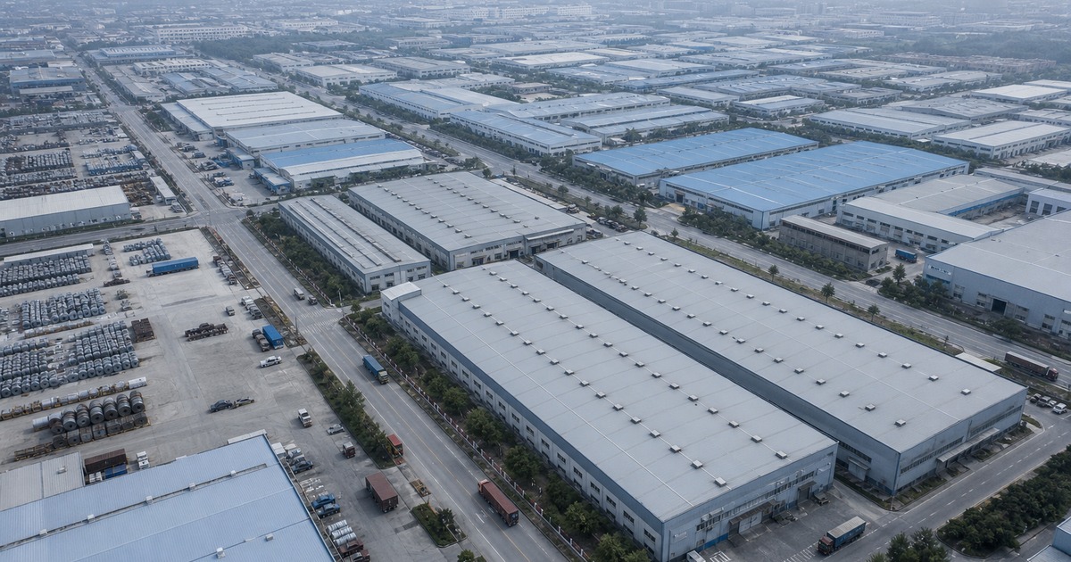
The point of this equipment isn’t the count; it is that every stage stays in one facility, so the process route is chosen for your part, not a subcontractor chain. Since 1999, we have delivered over 70,000 custom part numbers to 3,000+ companies in 100+ countries, with a 90.4% on-time delivery rate and a 5.0/5 customer satisfaction score. Send us your drawing — let us run the five stages for you.

FAQ
What are the five stages of sheet metal fabrication?
Cutting, forming, joining, finishing, and inspection. Cutting separates the blank from the raw sheet; forming gives it three-dimensional shape through bending, stamping, or deep drawing; joining assembles the parts by welding or mechanical fastening; finishing protects the surface and sets its appearance; inspection verifies the result against the drawing. The route adjusts with material, structure, quantity, and final application, but a quote that does not address all five stages is not describing the job that will actually be produced.
When should a part be laser cut rather than stamped?
It depends on volume and geometry. Laser cutting suits complex two-dimensional profiles at low to medium volumes, because the program can change without tooling. Stamping or blanking becomes the better route at high volumes, where a dedicated die spreads its cost across enough parts to beat the slower per-part cycle. The decision is economic as much as technical: the same geometry can be quoted very differently at a few hundred pieces and at tens of thousands, and the crossover point is where tooling starts to pay for itself.
Why is springback a problem in forming?
Because metal relaxes after it is bent, and the part springs back from the angle the tooling produced. Press-brake angle tolerances typically sit around ±0.5–1°, depending on material, thickness, bend length, tooling, and geometry. Springback is compensated by over-bending according to material data and trial results, which is why formed features drift more than cut features, and why the same drawing can behave differently in a different material batch. Stamping and deep drawing up to 400 tons control this better at volume, but not for free.
How do you decide between welding and mechanical fastening?
By what the assembly has to survive and how the parts must behave afterwards. MIG, TIG, spot, and laser welding create a permanent joint, but welding adds heat distortion that can move a tight dimension; mechanical methods such as rivets, PEM fasteners, and threaded inserts avoid that distortion entirely and allow disassembly. Where dimensional stability matters more than joint strength, mechanical fastening is often the safer route, and it should be decided at the design stage rather than after the first batch warps.
What does good inspection look like across the process?
Evidence at multiple points rather than a final check. A mature route verifies incoming material, confirms the first article against every critical dimension, checks in-process, and inspects the finished part, with batch reports and material certificates travelling with each shipment. Batch traceability is what lets you compare one delivery with the next and catch drift before it reaches assembly. Inspection at the end of the line can only reject a problem; inspection through the process prevents it.
From Sheet to Finished Part — Send Your Drawings Today
✅ Verified factory · Free samples · All five stages in-house
📩 tylor@xinjiuxinji.com — Reply in 3 working hours — free design optimization & quotation.
Free samples available for evaluation — Send your drawings now and verify before you commit
Sheet Metal Tolerances: Why Tighter Costs More